MIL-PRF-62368C(AT)
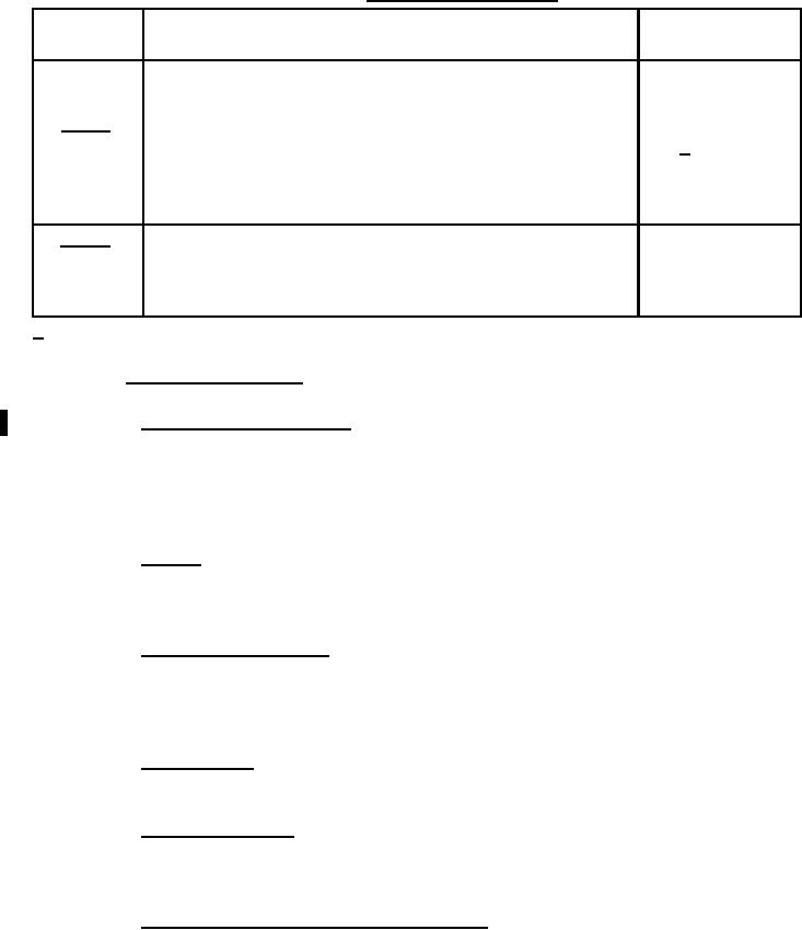
TABLE II. Classification of defects.
Method of
Category
Defect
examination
Critical
None
Major:
101
Dimensions affecting interchangeability, out of tolerance
SIE 1/
(see 3.3).
102
Improper identification marking (see 3.5).
Visual
103
Improper workmanship, affecting performance (see 3.6).
Visual
Minor:
201
Dimensions not affecting interchangeability, out of tolerance SIE
(see 3.3).
202
Improper workmanship affecting appearance (see 3.6).
Visual
1/ SIE = Standard Inspection Equipment.
4.5 Methods of inspection.
4.5.1 Materials and construction. Conformance to 3.2 through 3.3.4, shall be determined
by inspection of contractor records providing proof or certification that design, construction,
processing and materials conform to requirements. Applicable records shall include drawings,
specifications, design data, receiving inspection records, processing and quality control
standards, vendor catalogs and certifications, industry standards, test reports, and rating data.
4.5.2 Defects. Conformance to 3.3, 3.5 and 3.6, shall be determined by examination for
defects listed in table II. Examination shall be visual, tactile, or by measurement with standard
inspection equipment.
4.5.3 Rotation of output shaft. To determine conformance to 3.4.1, the motor shaft shall
rotate in a counterclockwise direction when viewed from the shaft end with positive voltage
applied to the + (positive) terminal of the filter and negative voltage applied to the - (negative)
terminal of the filter. Reverse lead polarity stated above and verify clockwise shaft rotation.
4.5.4 No load speed. To determine conformance to 3.4.2, the motor output shaft speed
measured with no load applied shall be no more than 36 rpm in both directions of rotation.
4.5.5 Zero torque current. To determine conformance to 3.4.3, the current drawn by the
motor under the condition of no load applied to the output shaft, shall be measured and shall not
exceed 0.5 A dc.
4.5.6 Speed and current at 640 oz-in. (4.52 N-m)). To determine conformance to 3.4.4,
the motor output shaft shall be connected to a loading device such as a dynamometer and a
speed-indicating device such as a tachometer. The loading shall then be adjusted to not less than
640 oz-in., and the resultant speed and current shall be measured for each direction of rotation.
The speed shall be no less than 22 rpm, and the current shall be no more than 1.5 A dc.
11
For Parts Inquires call Parts Hangar, Inc (727) 493-0744
© Copyright 2015 Integrated Publishing, Inc.
A Service Disabled Veteran Owned Small Business